

Micro store


JBD BMS 13S 14S 20A 30A 40A 50A 60A Smart BMS With Balance and UART/RS485
reviews
Item specifics
- Model Number:
- SP15S020
- Type:
- bms pcba
- Place of Origin:
- Guangdong, China
- Brand Name:
- JBD
- Supplier Type:
- manufacturer
- Copper Thickness:
- 1 oz
- Item No.:
- SP15S020
- name:
- BMS
- Current:
- 20A 30A 40A 50A 60A
- Voltage:
- 48V
- Same port:
- Yes
- Usage:
- Lithium Battery Packs
- Package:
- Standard Package
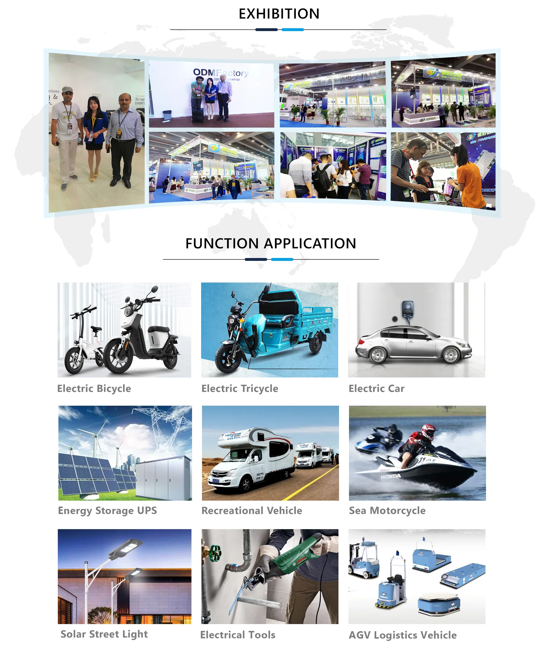
- Application:
- Electronic Products
- Testing:
- 100%testing
- MOQ:
- 5pcs
Description
Products Description
JBD-SP15S020
JBD-SP15S020 is an intelligent protection board scheme specially designed for 15 series battery packs of power battery, electric bicycle, electric motorcycle, etc. It is suitable for lithium batteries with different chemical properties, such as lithium ion, lithium polymer, lithium iron phosphate, etc. The protection board has strong load carrying capacity and the maximum continuous discharge current can reach 20A 30A 40A 50A 60A.
● 15 cell series protection
● Various protection functions for charging and discharging
● Discharge over current, short circuit protection functional processes of hardware
● Over voltage, under voltage, temperature and overload protection function processing of software
● Accurate SOC calculation with automatic SOC learning function
● Reserved RS485 communication function
● UART communication function
● The reserved switch controls the output of protection board
● Hardware discharge over-current, short-circuit protection function processing
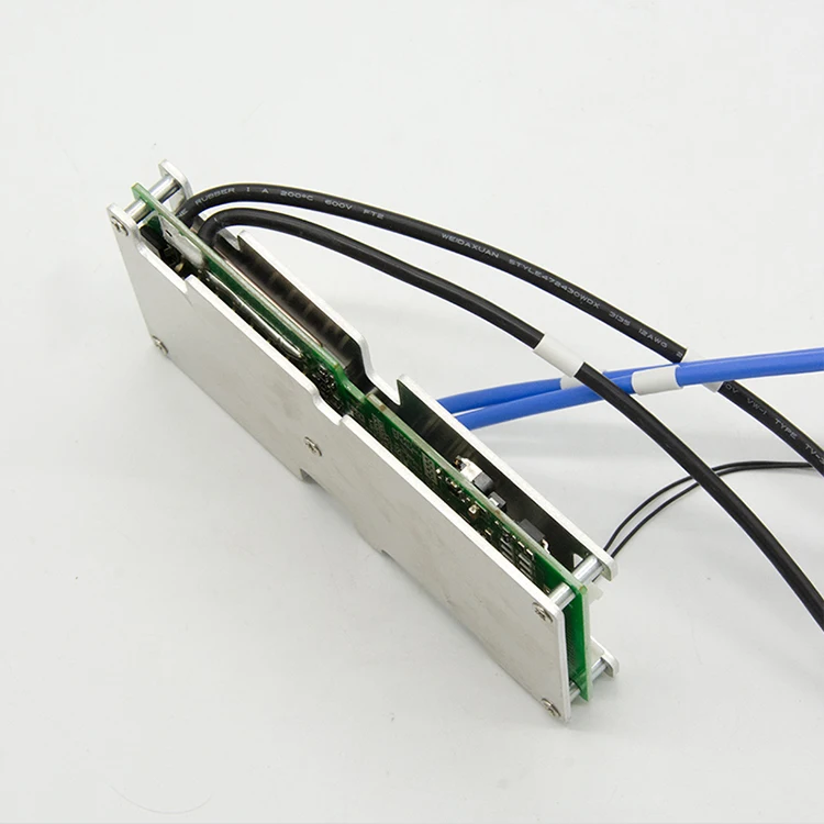

Detailed Images
Operating voltage range | 35.1-55.25V |
Operating current (MAX) | 40A 60A 20A 30A 50A |
Over-charge protection voltage | 4.25±0.05V |
Over-discharge protection voltage | 2.7±0.1V |
Balanced turn-on voltage | 4.0±0.05V |
Charging over current protection value | 60A |
High temperature protection value of charging | 65±2℃ |
High temperature protection value of discharge | 75±2℃ |
Internal resistance | <10mΩ |
Protection function description
Overcharge protection: When the battery is under the charging state, the voltage keeps going up. When the protection board detects that the voltage of any cell is higher than the overcharge protection value, the protection board will start timing immediately. When the time reaches the overcharge protection delay, the protection board will turn off the charging MOS tube, at that time, it cannot be charged.
Overcharge protection recovery: After the overvoltage protection appears on the protection board, the battery voltage will going down under the static or discharge state of the battery. When the protection board detects that each voltage is lower than the recovery voltage of the overcharge protection, the protection board will output a signal and turn on the charging MOS tube to charge.
Over-discharge protection: When the battery is under the discharge state, the voltage keeps going down. When the protection board detects that the voltage of any cell is lower than the overcharge protection value, the protection board will start timing immediately. When the time reaches the over discharge protection delay, the output signal of the protection board will turn off the discharge MOS tube, the load lock circuit will work, but, it cannot discharge at this time.
Over discharge protection recovery: After the over discharge protection appears on the protection board, the battery voltage will going up under the static or discharge state of the battery. When the protection board detects that each voltage is higher than the recovery voltage of the over discharge protection. At this time, disconnect the load or charge, the protection board will output a signal and turn on the charging MOS tube to charge.
Overcurrent protection: When the battery is under the static or discharge state, the current suddenly increases. When the protection board detects that the current reaches the overcurrent protection value, the protection board will start timing at that time. When the current duration in the circuit reaches the overcurrent protection delay time, the output signal of the protection board will turn off the discharge MOS tube, and the load lock circuit will work. At this time, the discharge cannot be conducted.
Overcurrent protection recovery: After the discharge overcurrent protection appears on the protection board, the discharge MOS tube is turned off, and the current in the loop becomes 0. At this time, the load is disconnected or charged, the output signal of the protection board will turn on the discharge MOS tube to discharge.
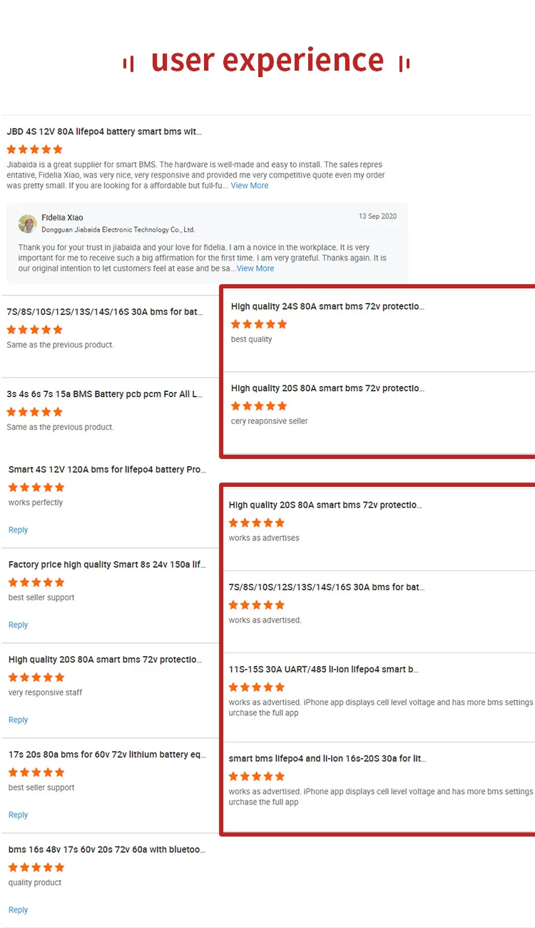
Customers Satisfaction
Details Images
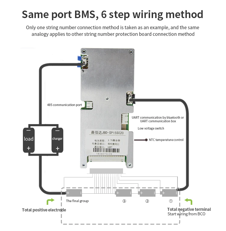
matters need attention.
Please note:When assembling the wiring, weld the cable and the cell correctly, connect the B- of the PCM with the total negative pole of the cell, and then insert the cable into the needle base on the PCM. (Note: different connection modes for different strings, and different connection modes for the same port)
Recommend Products
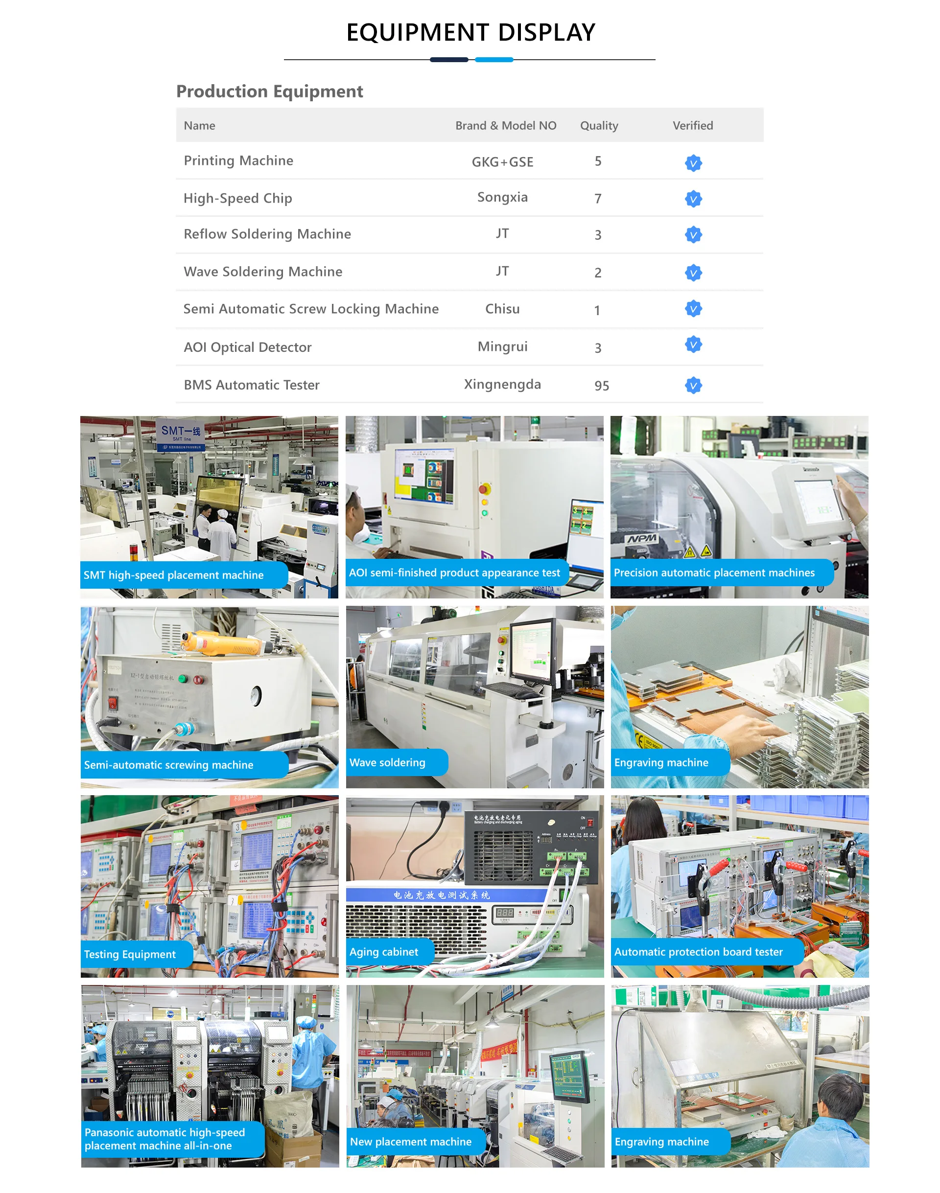
Company Profile


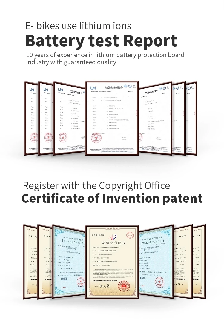
Certifications
Package


FAQ
1. What type of charger should I choose?
Lithium battery must choose specific charger, do not use Charger for Leadacid battery, for leadacid charger may have MOS with high pressure breakdown protection, which will not protect of BMS over charge. LifePo4 battery charger voltage=battery string No.X3.6V, while Li-ion battery charger voltage=Battery string No.X4.2V.
2.The relationship between Battery capacity and BMS current?
There is no direct relationship between Battery capacity and BMS current, big capacity doesn`t mean a big battery, but rely on continue current, that is to say if your engine is powerful, your should choose high current of BMS, it is not relied on batterycapacity.
3.Whether my BMS damaged?
If you want to judge if the BMS is damaged, please take the folowing steps, to test if each cell voltage is the same with voltmeter? if the cell voltage difference is over 1.0V, the fault is displayed that it cannot run far, no power supply at the start range, short charge time, all these issues are almost caused by battery cells, if BMS damaged is displyed as no charge, no discharge, no discharge while the battery has voltage.
4. Do you produce Hardware BMS or Smart BMS?
We produce both Hardware bms and smart bms.
5. What accessories should i buy for smart BMS?
We have bluetooth module for App use, and communication box tool(UART/RS485) for PC use.
And LCD display (UART/RS485) available too. Further question, please contact our customer service.
bset seller


BEST yyu


YUIO


Relevant products


